Integration Testing and Troubleshooting
- Jordan Carlson
- Jul 17, 2022
- 3 min read
Updated: Jul 30, 2022
Each step in the development process resulted in new challenges that required strict attention to detail in order to keep the full development cycle continuing, then to ensure the final product met expectations, requirements for the projects goals, and also followed the constraints to ensure the feasibility of the project for the requirements to be fulfilled following realistic expectations for the implementation.
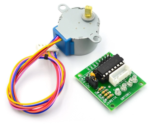
The stepper motor on the right, the 28BYJ-48 and its inexpensive motor driver alongside it, the ULN2003 was the first tested component. This test did not go well, as the motor did not pull enough torque to meet our required tension between the magnet array and the motor for tension control, so this original idea needed to be discarded to make way for the servo motor iteration attempt. Testing the servo motor resulted in excellent performance, particularly in that it could lift approximately 6.3kg, as tested with lifting potatoes, which is much more than enough to pull the magnet array, plus more tension in the future if the users demanded an additional challenge. This was also at a relatively low package size, and testing the range with different PWM settings in firmware resulted in increased confidence with this solution.

Mechanical considerations for the mounting of the device was strict as
well. There are only a few holes on the frame of the under-desk bike for usage without potentially compromising the frame structure. Therefore we sought out to use very small machine screw, such as small M3, M4, and M5 screws, and with testing these proved to be suboptimal for mounting with the very strict constraints. 3D printing would be a more flexible option, as the exact size up to a resolution of 0.3mm could be printed to mount the servo motor to the frame of the bike, and the same material could be used for the actual actuator, and the PCB mounting could be less rigid because of the lack of motion the PCB encounters, and thus it could be glued, taped, or zip-stripped to place if necessary, or a mounted spot based on the frame structure could be selected based on a simple structural analysis of the under-desk bike frame.

The servo motor was a relatively large package size, but it could fit within the middle of the generator or frame, or between the outside of the frame and the enclosure. Upon inspection of the mounting options within the frame, the safer and more durable option would be to mount the frame on the side of the bike with the actuator extending to within the under-desk bike frame to be set for straight and mechanically efficient actuation.
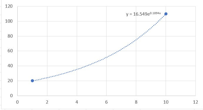
With all components in place, the question remained how to set the firmware for optimal user experience and thus product quality. Upon testing, it became very clear that a linear solution of degrees of servo rotation resulted in a much higher jump in tension intensity in the higher range of degrees as this is when the magnets became exponentially more effective in affecting the pedaling speed. So the firmware interprets the degree in rotation to be smaller as the numbers increase, representative as an inverse logarithm, or an exponential as shown in the above graph, with decreasing degrees of rotation within the servo motor. This final test and

then full user experience was summed up in the dashboard created on the left, and additional features were added such as the three automatic tension adjustment modes that reflect the speed in automatic tension adjustment.
The final tests showed that, as long as the user pedaled above the power threshold, 7.5V, the Bluetooth will successfully react to user control, and will notify the user upon these changes, and the tension controller will behave exactly as outlined until we modify or add new features.


Comments