PCB Design and Testing
- Duncan Cairns
- Jul 17, 2022
- 1 min read
Updated: Jul 29, 2022
All of the circuity and PCB design was done using EasyEDA [1][2]. The microcontroller is powered from an external computer which is used so that the microcontroller does not lose power when the user stops pedaling. This issue has already been solved by Ergonomyx by using a battery and is therefore considered out of the scope of this project. A block diagram of the circuitry is shown below.

The circuitry and the corresponding PCB is composed of the microcontroller, 3.3V regulation for the microcontroller, a AC-DC half-bridge rectifier, regulation components to step the high-voltage from the generator down to 5V, a volt-meter for real time voltage level feedback, and PWM logic circuitry. A USB-TTL converter is used from the UART data lines to boot the code and display serial information on the computer. This is an external component that did not need to be designed or added onto the PCB.
The circuit can be split into both the circuitry required for the 3-phase generator and the circuitry required for the microcontroller. Both of these circuits are almost independent of one another as the 3-phase generator is only used for generating the power for the motor. The microcontroller circuitry is shown below.
Microcontroller circuitry

In order to boot code to the ESP32 the serial header is needed to communicate with the computer through a USB-TTL converter. Boot and Reset buttons are also required for loading the code and resetting the ESP32. The 3V3 regulator steps down the 5V from the computer to 3.3V for the microcontroller as the ESP32 only runs off of 3.3V. Transient protection and power LED were added as well for microcontroller protection and to determine if the voltage is applied throughout the PCB properly.
3-phase generator circuitry
Because the MG996R DC servo motor requires the same voltage for power and the PWM line a level shifter for the PWM logic is required. The initial voltage out of the ESP32 is 3.3V. Although 7V is generated from the generator to power the motor. This circuit was designed so that the signal would be transmitted to the motor at the same frequency well stepping up the voltage. This was simulated in LTSpice and shown below.
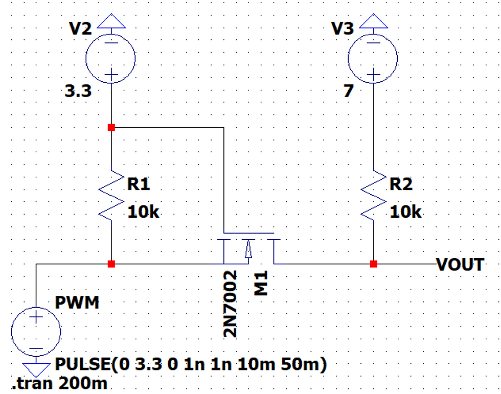
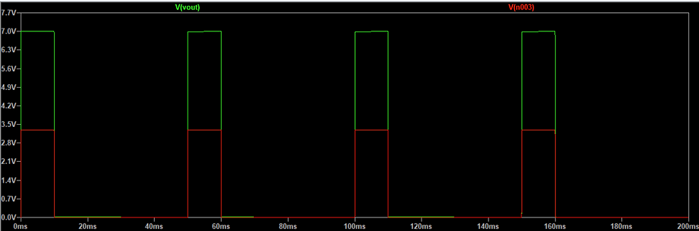
As shown above the figures this circuit uses a N-MOSFET to turn on and off depending on the input PWM signal. If the voltage is logic low then the MOSFET turns off and blocks the signal out of the drain. If the PWM signal is logic high then the MOSFET is switched on and is pulled up to 7V through a 10k pull-up resistor. It was shown through simulations that a 2N7002 N-MOSFET would switch fast enough at the required frequency to not warp the output signals. This level-shifted PWM signal is then sent directly to the DC-servo motor.
The Generator circuitry used to power the DC servo motor is shown below

The 3-phase generator is fed directly into the half-bridge rectifier to convert the AC voltage to DC. It then goes through eight capacitors in parallel for smoothing separated by ferrite beads to filter out high-frequency noise from the generator. These capacitor values and the configuration were suggested by Ergonomyx for their current generator and were tested thoroughly [3] . This circuit was also simulated in LTSpice and shown below.


This shows how the rectifier smooths the output of a three-phase voltage source with 80Vpp shown by the red line after the rectifier. This simulation was run under similar conditions by using a 5V regulator into a resistive/inductive load to simulate a motor.
The buck converter used accepts voltages from 5V - 45V [4] This will accept most of the common voltages generated. The buck converter can step down the voltage to 3.3V - 5V depending on the design of the external resistors in the buck converter circuit. This component can deliver over 1A of current at 5V which is enough to supply the DC servo motor. The buck converter also has an efficiency of 80% [4] .
After the voltage out of the generator is rectified it is connected to a voltage divider to decrease the voltage ~10x. It is then fed into an op-amp to act as an impedance buffer before it is connected to the microcontroller. An on-board ADC on the ESP32 can then read the voltage and use the ADC values to determine if the generator is providing substantial power to drive the motor. This feedback is useful for the control system positioning design which can be found in the firmware section.
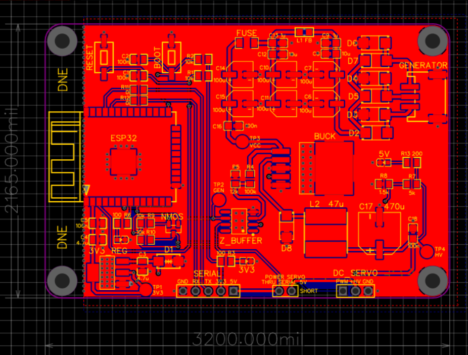
The PCB wiring was also done in EasyEDA

Unsoldered PCB:

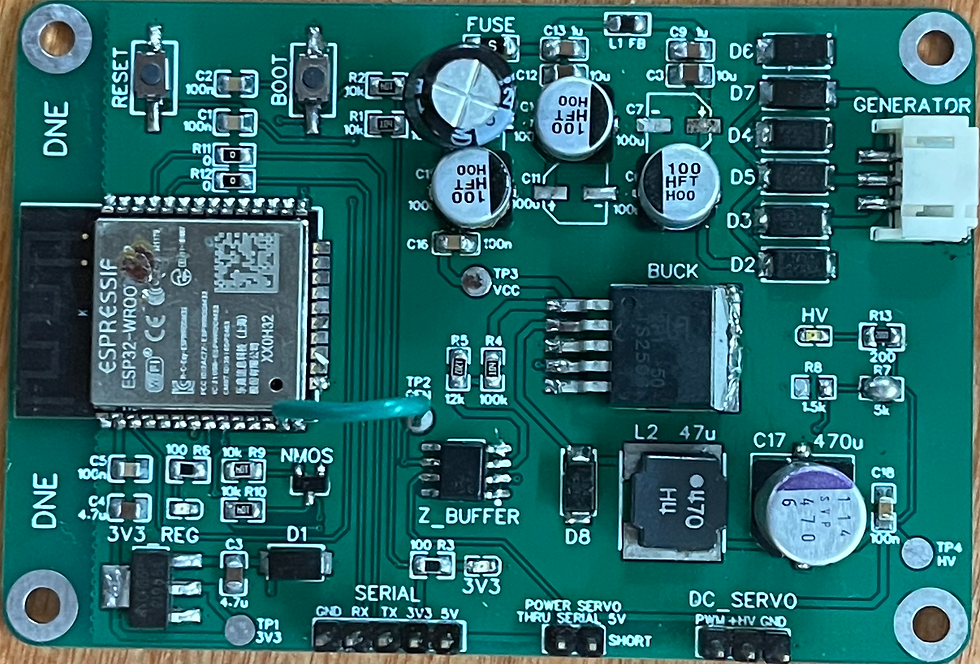
Soldered PCB:


Comments