Mechanical Design
- Steven Dashuck
- Jul 28, 2022
- 2 min read
Updated: Jul 30, 2022
Prior to the mechanical design and subsequent modelling of parts, an accurate representation of the existing bike structure had to be constructed to provide a baseline. Images of the bike were taken from the relevant normal angles to the frame with a ruler for scale. These images were then placed inside SolidWorks sketches, and using its image scaling and rotation tools, 1:1 scale was achieved [5].

With the images then placed, sketches could be created directly on top of them, reducing the need to measure every feature, some of which were in difficult locations.

Once the bike structure was correctly modelled, the mechanical design could begin, informed by the team’s testing of motor and servo mechanisms for moving the magnetic brake. A rigid wire was decided on as the linkage to a servo motor, which dictated the possible mounting positions for the servo. The team decided on using 3D printed parts for their low cost and ease of production, which added the challenge of making all parts compatible with the printing process. This meant avoiding long unsupported spans over the print bed and ensuring a flat surface to begin the print with no downward facing features.
Using the existing bike model, a mounting mechanism was then adapted to fit the bike frame with provisioning for the servo’s mounting as described by its specifications sheet [6].


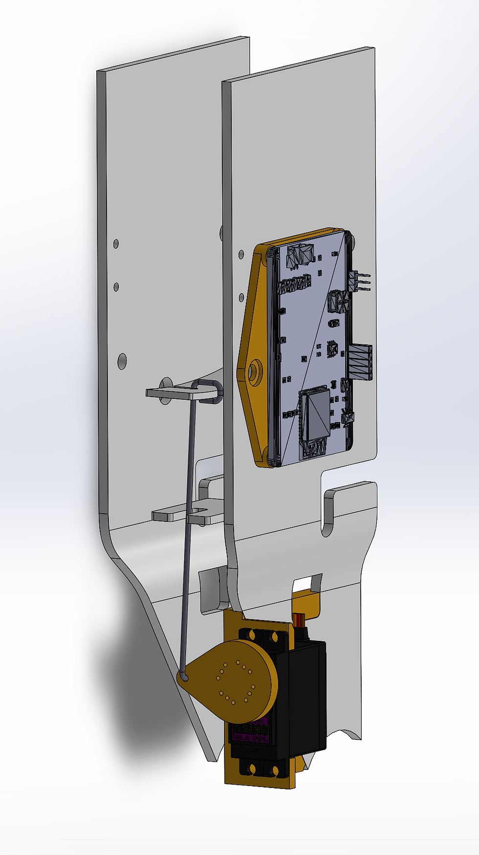
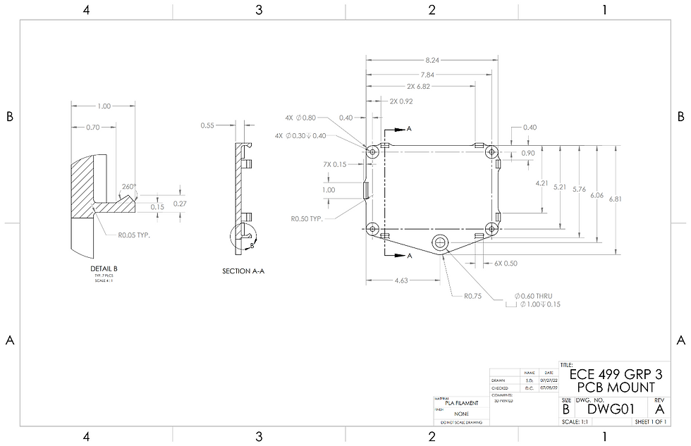
An actuator to extend the servo’s effective radius was also designed, with its path of motion carefully accounted for to avoid collisions with existing bike structure and provide an adequate range of motion for the magnetic brake. To mount the PCB, another 3D-printed part was required, again utilizing the model of the existing bike’s frame to identify suitable locations and mounting hardware. It was decided to use an existing fastener position on the side of the frame rail in an open position. Due to the difficulty of using fasteners in these locations, spring tabs were used to hold the PCB, easing installation.
Before printing the parts, all outlines were printed to scale and test-fit on the bike to ensure there were no interference issues and correct any measurement errors. With the part designs completed, they were then printed from PLA with the larger ones taking close to 4 hours, and test fit on the bike. Some of the fine holes needed to be drilled out due to low resolution of the printer, but all parts achieved satisfactory fit and function.
The files for the 3D printing can be used with any 3D printer, and can be downloaded below. To use these files, the .txt file extension must be removed:
For the Servo Motor Mount:
For the Servo Motor Actuator Adapter Attachment:
For the PCB Mount:


Comments